How to build a Nixie clock
 Here you will find all the information you'll need to build a DCF77 radio controlled Nixie clock. In case you're not familiar with either Nixie tubes or the DCF77 time signal, you might go here (Nixies) or here (DCF77) for an introduction.
When I first saw one of those clocks in a shop in Freiburg, it was obvious that I needed one of them. But I did not want to spend EUR 249.- on something I knew I could do myself. I then checked the WWW for DIY Nixie clocks. There are some, but none was DCF77 controlled and totally free. So I started my own project. If you want to make your own, you can download everything you need (apart from the hardware of course ;-) from this site.
News
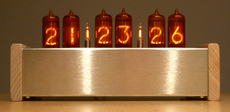
03.01.05: the case is finally finished. Laser cut holes for the tubes, stainless steel and beech wood for the case. Looks really nice.
21.12.03: Important: I built a second clock and found a small oops in the PCB layout. The first batch of ZM1210 I got had no legs at pin 9 (second anode pin), so I used this pad as a via to pin 7 (digit 5). The ZM1210 I bought now do have this leg and it took me some time to find out why all digits were pulled low. So if nothing happens in your nixies check whether you have this pin and just cut it (I marked the place with red circles on the layout).
18.11.03: after a lot of testing, I declare the software ready for clock use. I also added a power-on tube test.
02.11.03: I updated the μC software - no more choking on the time ;-)
Overview
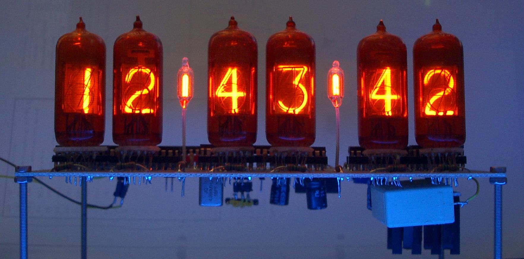
 My design uses 6 ZM1210 Nixie tubes I bought from Ask Jan first! to display the time, date and temperature (not yet implemented). Everything is controlled by a cheap Atmel 4433 or Mega8 microcontroller. The μC is in-circuit programmable to allow easy software updates via the parallel port. All the other parts on the part list are standard, with the possible exception of the MC34063 used for the high voltage generation. I got mine from Reichelt in Germany. The HV is controllable by the μC via a small reed relay (optional) and if a Mega8 is used, the I2C bus is accessible with a pin header to add an temperature sensor like the LM92 for example. The display output to the tubes is going to three 74LS373 8bit latches which drive a 74141 for each Nixie. But probably it's easiest to just take a look at the schematic to get an idea.
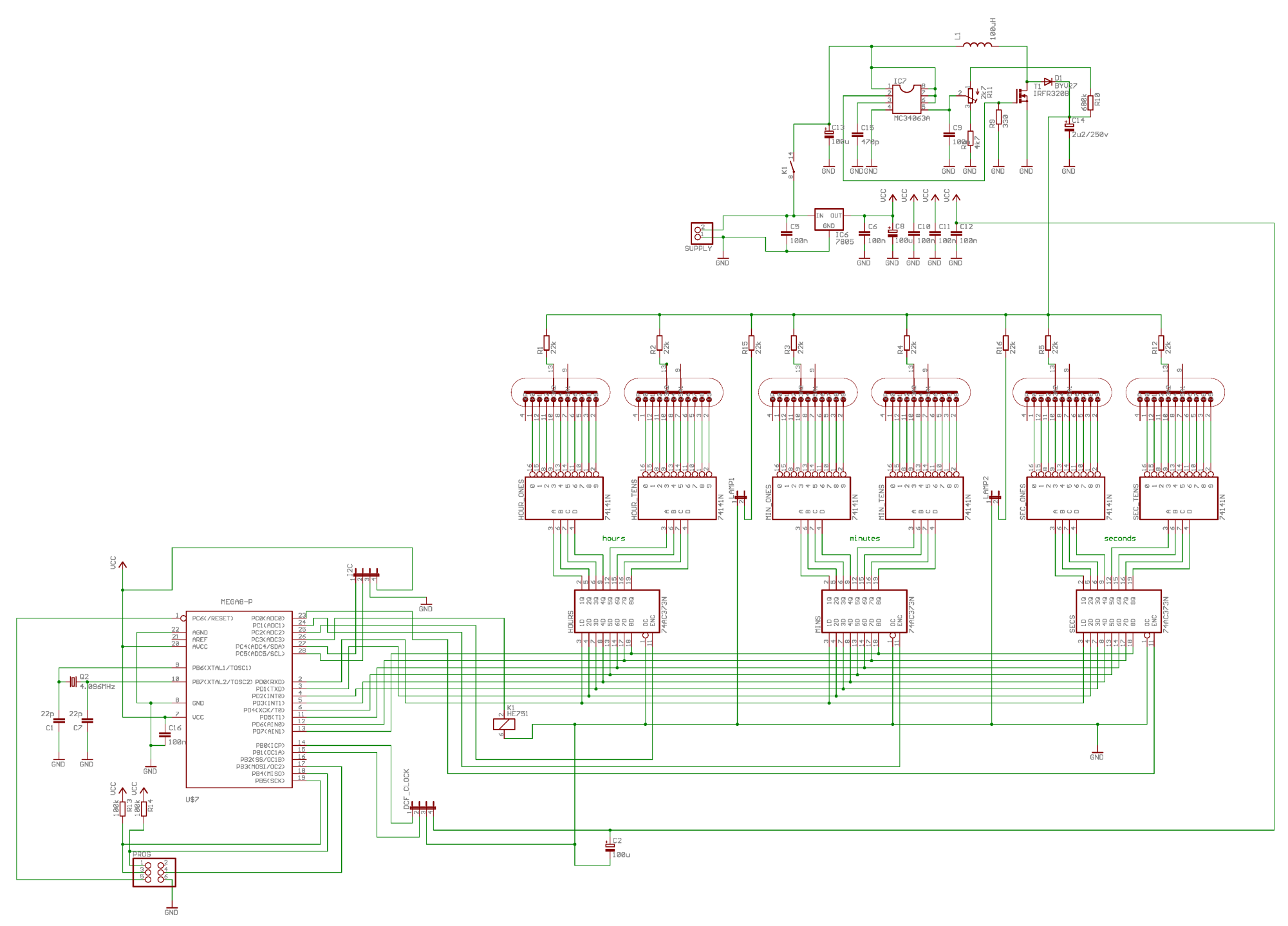
In the top part one can see the HV generation, below are the Nixie tubes and their drivers. In the lower left the μC with its helpers.
Hardware
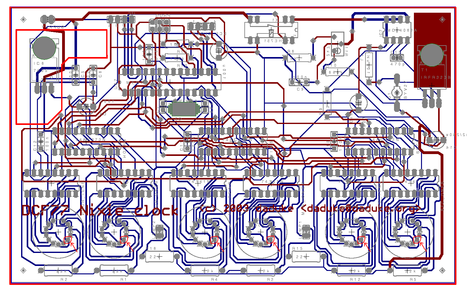
The schematic and PCB layout were created using Eagle. The PCB I came up with is a two-sided layout in Euro format (160x100 mm2) and about 30 vias.
If you want to print transparencies to make your own PCB, you can find Postscript files of the top and bottom layer, the parts and the vias here.
The whole circuit runs with one single 9..12 V supply voltage (pin 1 = GND, pin 2 = Vcc on "SUPPLY"). The 5 V for the electronics and the HV for the nixies are generated onboard.
Software
The decoding of the DCF77 signal and the clock itself is done by a C program I wrote for the Atmel. I used the Atmel port of gcc to compile the program. To get this environment up and running, head over to this site and download the items at "Software installation". Also get their test program, unpack it and try "make". This should run without a problem. If you now connect the hardware you built to your parallel port using the following wiring:
| Pin on Nixie clock programming port | Pin on parallel port |
|---|---|
| Reset (5) | Init (16) |
| MOSI (4) | D0 (2) |
| MISO (1) | Busy (11) |
| SCK (3) | Strobe (1) |
| GND (6) | GND (18) |
and copy my avrledtest.c to the directory with the test program, you can compile and transfer the program with "make load".
DCF77
But where does the time come from? The easiest and cheapest way to get a DCF77 signal is to buy a radio controlled alarm clock in some discounter (EUR 7.- or something) and then try to find the signal path carrying the DCF77 signal between the reception and the clock circuit. In all modules I have seen so far, this signal is inverted which means that the idle state is high and the bits are low. This is why in line 47 of the program it says dcf_in = (uint8_t)bit_is_clear(PINB,1);. If you have the opposite, you have to change that to "bit_is_set". The wire then goes to pin2 of DCF_CLOCK, pin3 is GND and pin4 is +5 V supply. Pin1 is not used at the moment.
Questions & comments
I most probably have forgotten a million things that are important or helpful when building this Nixie clock. So if you have any questions or comments or want to send me a picture of the clock you built, please don't hesitate to send an email to daduke@daduke.org. I'd like to hear from you.
archive of all files for this project
all images  - last change: 2014/02/18
- last change: 2014/02/18
a 2025 daduke production. all rights reserved.